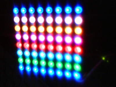
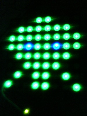
I’ve started playing with the Arduino platform and is really amazing the possibilities that this open source platform can offer, from beginners to more experienced users!
Recently, I’ve ordered Rainbowduino and a 8×8 RGB led matrix. Rainbowduino is essentially an Arduino designed for controlling an 8×8 RGB led matrix, with some features (I2C protocol suport, cascading).
Let’s get to work!
The first problem that I faced was to make it work: I don’t have a serial port (and rainbowduino cannot be connected via USB, as Arduino does), after 1min search in google, I found this post, with good instructions about how to use Arduino as a host for programming it. In the same page, you can find the mtXcontrol program, very useful for starting drawing with your rainbowduino!
The short instructions are:
1- Check the necessary materials
- Arduino with 328 chip (it will not work with model 168)
- Some wires
- Rainbowduino + 8×8 rgb matrix
2- Connect all cables as described in the web:
(Arduino) Reset <-> (Rainblowduino) DTR
(Arduino) 5V <-> (Rainblowduino) VCC
(Arduino) GND <-> (Rainblowduino) GND
(Arduino) TX <-> (Rainblowduino) TX
(Arduino) RX <-> (Rainblowduino) RX
3- Plug the USB cable to the Arduino, Start the Arduino IDE, and select the 328 model and upload a blank sketch:
/* blank sketch to upload on Arduino */
void setup()
{
}

void loop()
{
}
4- Now change the model to 168, and upload the firmware to the Rainbowduino and execute mtXcontrol!! and you’re done!
8×8 pixels never were so impressive!!


Hi,
I am using the latest files from, the firmware is dated 8/2/2011 from the githup site zip file “latest_mtxcontro_and_firmware_windows”, Seeeduino 328, and Windows XP.
I’m new to Rainbowduino….I was able to successfully the following using the Adruino IDE:
1. Blank the Seeeduino Atmega328 (I am using it as a pass a USB-serial comunication to the Rainbowduino board.)
2. Upload the “Rainbow_Plasma.pde” into the Rainboeduino and watch it perform in Standalone mode.
3. Blank out the “Rainbow_Plasma” from the Rainbowduino and watch the display turn off.
4. Upload the firmware the “mtxfirmware.pde” into the Rainbowduino and watch it all go white.
The problem is it seems that the”mtXcontrol.exe” does not seem to work. There is a message at the top of the window that says “No output device found, running in standalone mode”. I do not know what that means and how to correct it. Please help!!!!
ortsac
Yes this looks so easy but I can not get the firmware to even compile it fails
like all the other sketches i have tried I get an error every time firmware.cpp:12:22 MsTimer2.h: no such file or diectory.
firmware.cpp In function ‘void start ()’:
firmware:61 error: ‘Mstimer2 has no been declared
firmware.cpp In function ‘void stop ()’:
firmware:66: error: ‘Mstimer2’has not been declared
firmware.cpp: In function ‘void set_fram_delay(long int)’:
firmware:75 error:’MsTimer2″has not been declared
how do you declare this ,this was downloaded and put into the IDE library
how hard can it be to get the 4x4x4 led cube running. thanks
Russel, put the files MsTimer2.cpp and MsTimer2 from the mtXcontrol zip to a folder MsTimer2 under the libraries folder where your arduino ide is installed. Restart the Arduino IDE and the sketch should compile.
hi, i cannot get MTX control or any firmware for that matter onto the Rainbowduino, im using an arduino uno as a patch through to a rainbowduino v2, ive tried everything and it has failed so far, what can i do?
nevermind, i got the firmware to upload, but mtxcontrol says there is no devices found, what do i do to fix that?